Kincaid Arcade Bronzeage Video Game Test Rig
If anybody is interested in making something similar to this, I have added a wiring diagram to the Downloads page.
This was a project that I did a couple of weeks before I bought Jet Fighter. I had been thinking about getting a new board for awhile, and was thinking of upgrading my previous test rigs. I wanted to make the test rigs good enough so that I could play each game with somebody else relatively easily. Unfortunately, doing research on the price of the controls (joysticks, buttons, and whatnot) showed that doing that would cost a lot. I didn't really know what to do.
Left: My old test rig for QWAK! Right: My old test rig for Anti-Aircraft.
One day, I was feeling particularly bored, so I went on a couple of websites run by other collectors to see if they had been doing anything interesting. An article on arcade72 with the picture of a Kurz-Kasch TF-650 caught my eye.
Interesting. It's a test rig system that has all of the controls and power supplies mounted in a convenient box. It connects to various game PCBs by inserting fingerboards with some traces connecting different pins and a card edge connector. I figured that I could do something better.
The very first thing I did was figure out what controls it was going to have. I knew I would need a joystick for games like Gotcha and Space Race, and I figured it would be good to have a joystick with a button for games like Tank and Jet Fighter. Then there were games like Steeplechase and Anti-Aircraft which had a massive amount of buttons. I also had some pong clones, so I'd need paddle controllers. Lastly, every game had start buttons and credit switches.
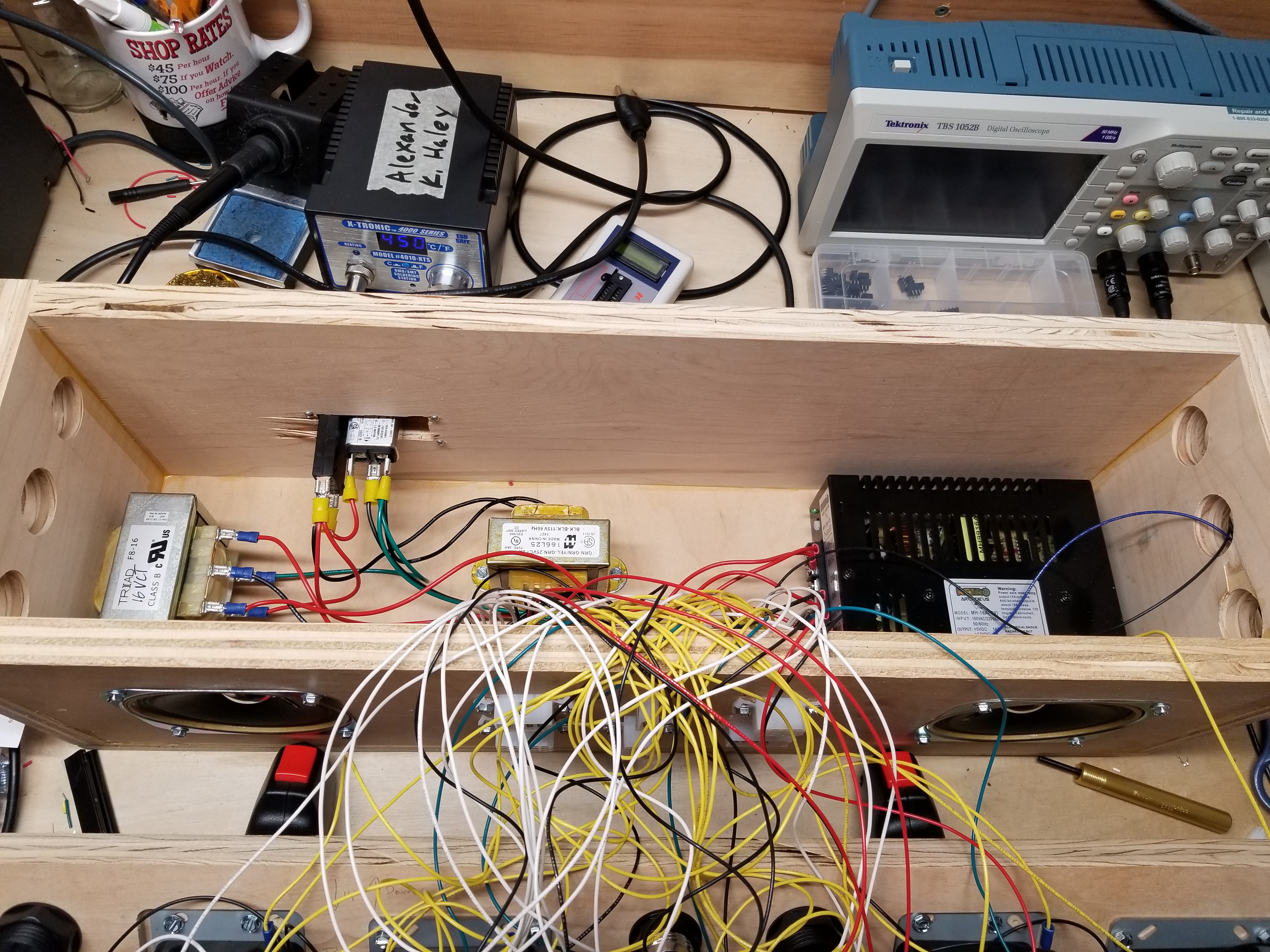
Powering the boards would be easy. Every bronzeage Atari game I knew of used a standard 16VAC CT and a 25VAC CT transformer to power the board and sounds. I was still wary of the amount of heat the regulators and bypass resistors generated on those old boards, so I added a retroarcade.us switching power supply to provide the 5v for the logic. This way, I had the option to remove or keep the regulator and bypass resistor by just adding or removing a 5v line on the adapter for the specific game.
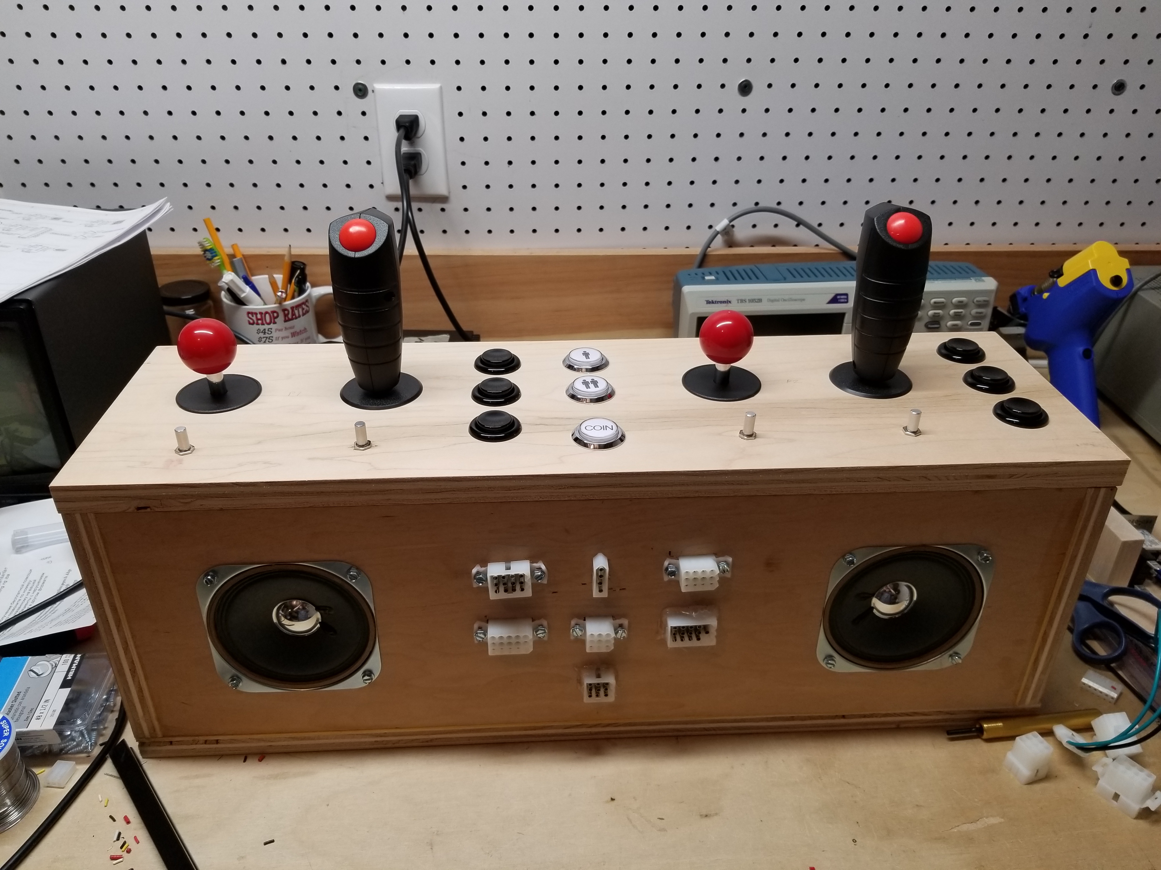
Then there was the issue of coming up with an enclosure for everything. I will admit, my test rig box is a bit of a beast at 24" wide by 8.5" tall and 7" deep. However, with that really large size comes the ability to comfortably fit two players side-by-side and use real controls, so I'd say it's worth it.
The last issue was how I wanted to hook up my boards to my test rig. I figured that having quickturnpcb fabricate fingerboards for me to make adapters would be too expensive. In the end, I settled on using molex connectors. They were relatively cheap, I had a bunch of them on hand, and I could use the male and female ends to ensure that I never stuck anything in the wrong spot.
With all that figured out, I got my dad to cut some scrap boards and I got to work:
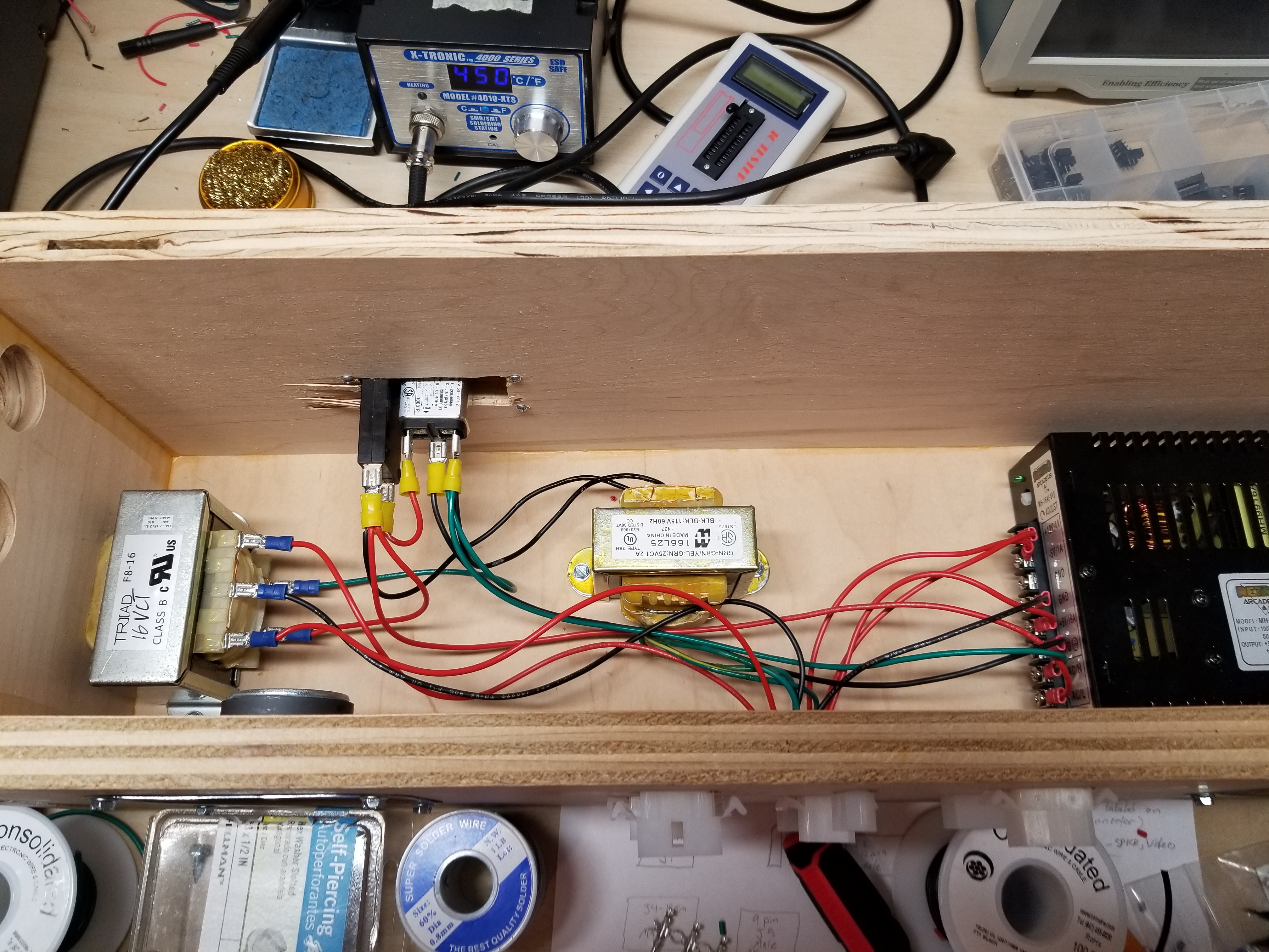
Wiring up the power supplies was relatively easy. It was nothing I hadn't done many times before.
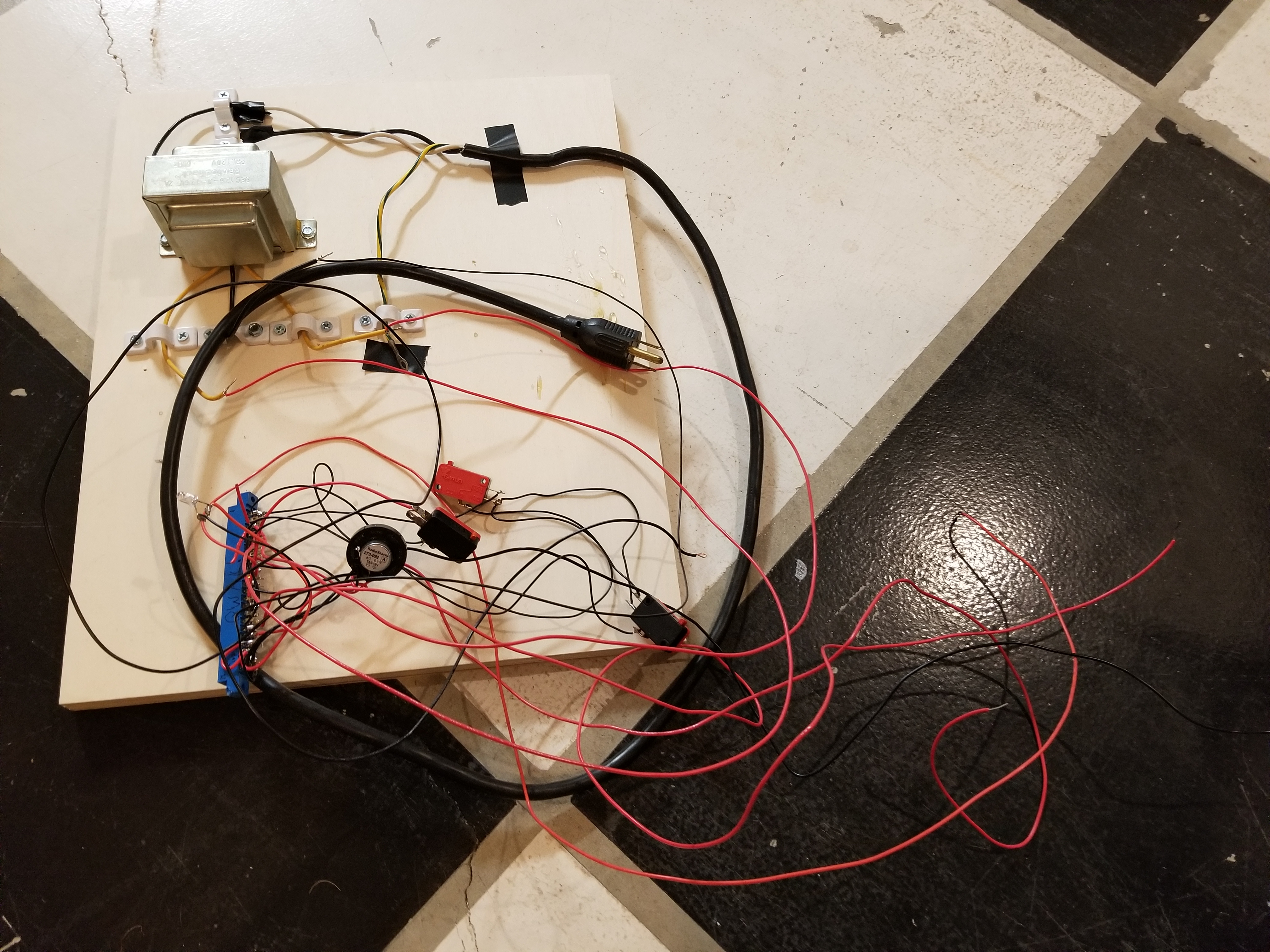
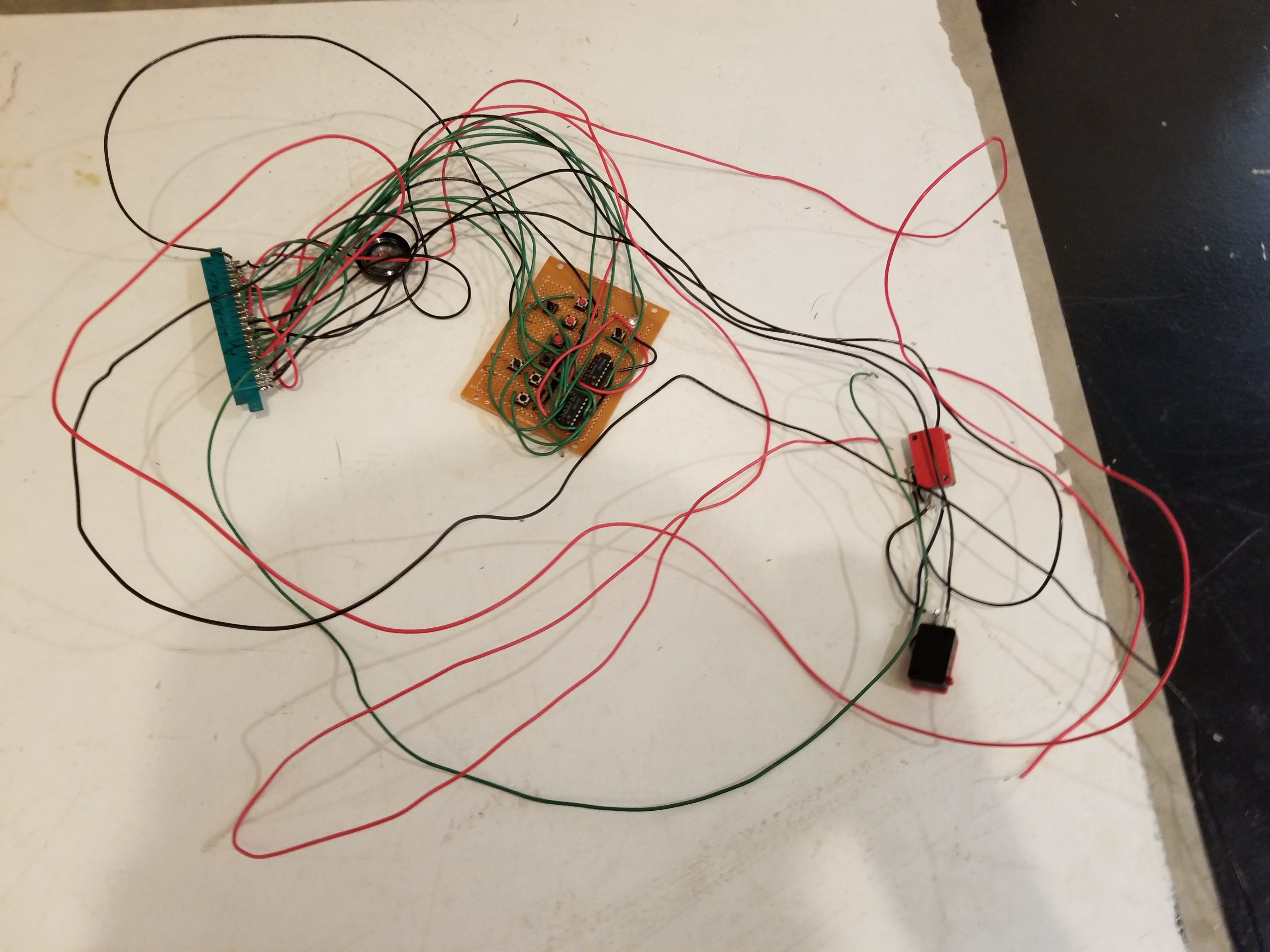
Wiring up all of the controls was a whole different animal. I had figured out what connectors would have what on them, but I hadn't figured out what pins they would correspond to. I placed each wire in a way that would make sense later, and wrote it down on a little sheet I made. Eventually, I had everything wired up:
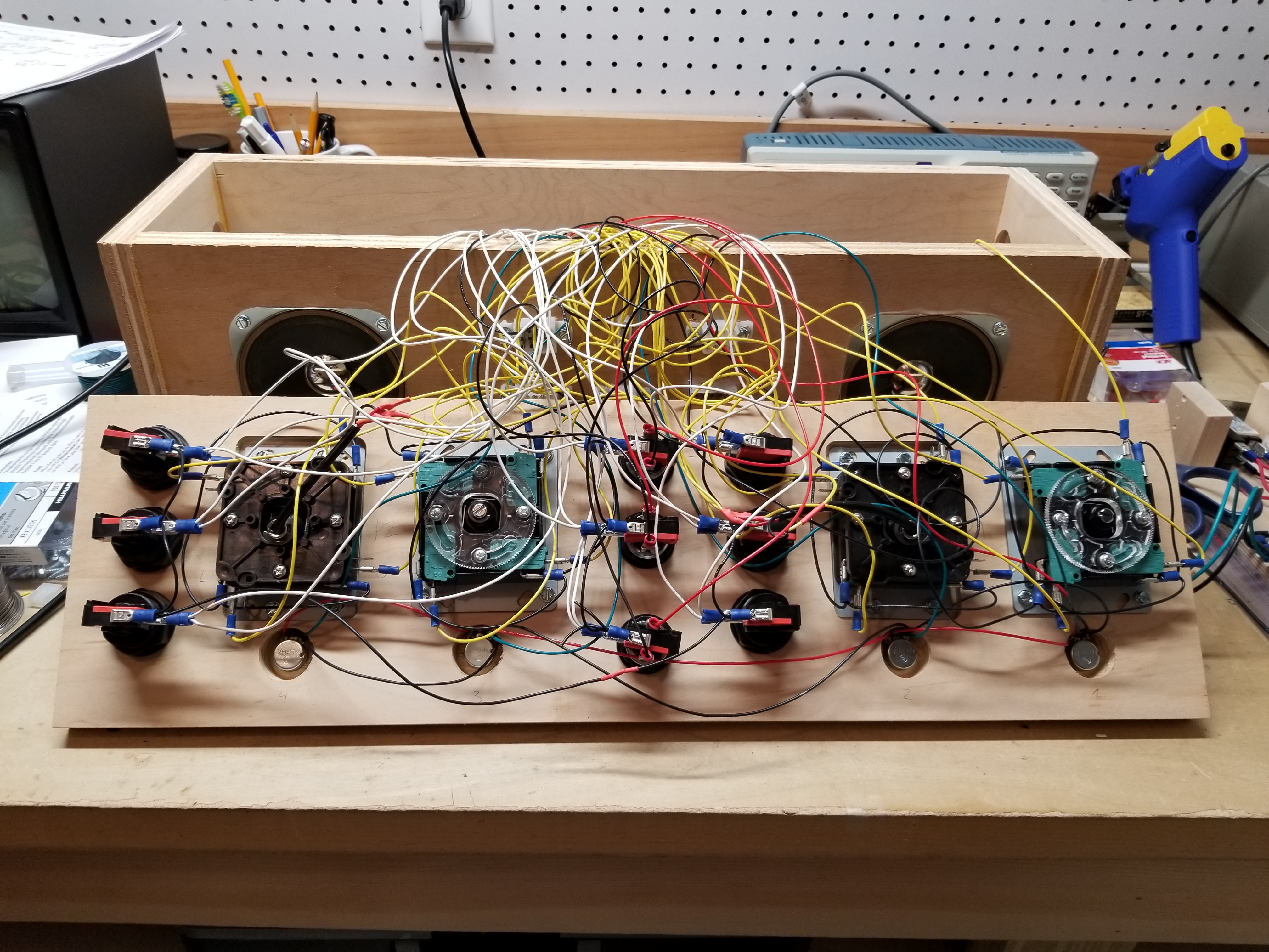
So many wires...
I fitted the control panel in place and added hinges so I would have easy access to everything inside in case I made any mistakes. As it turned out, there were none whatsoever.
The finished test rig.
Pictures:
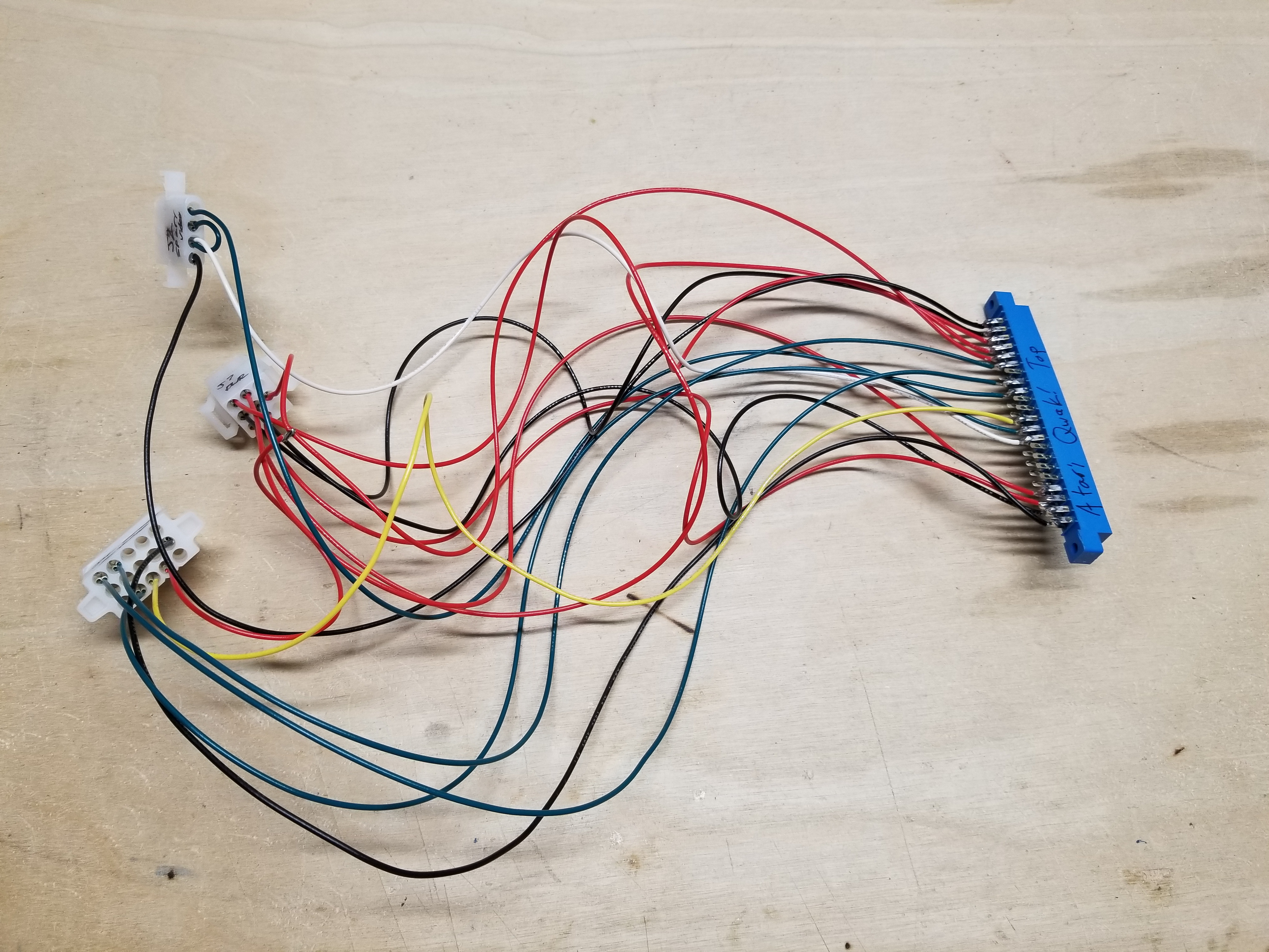
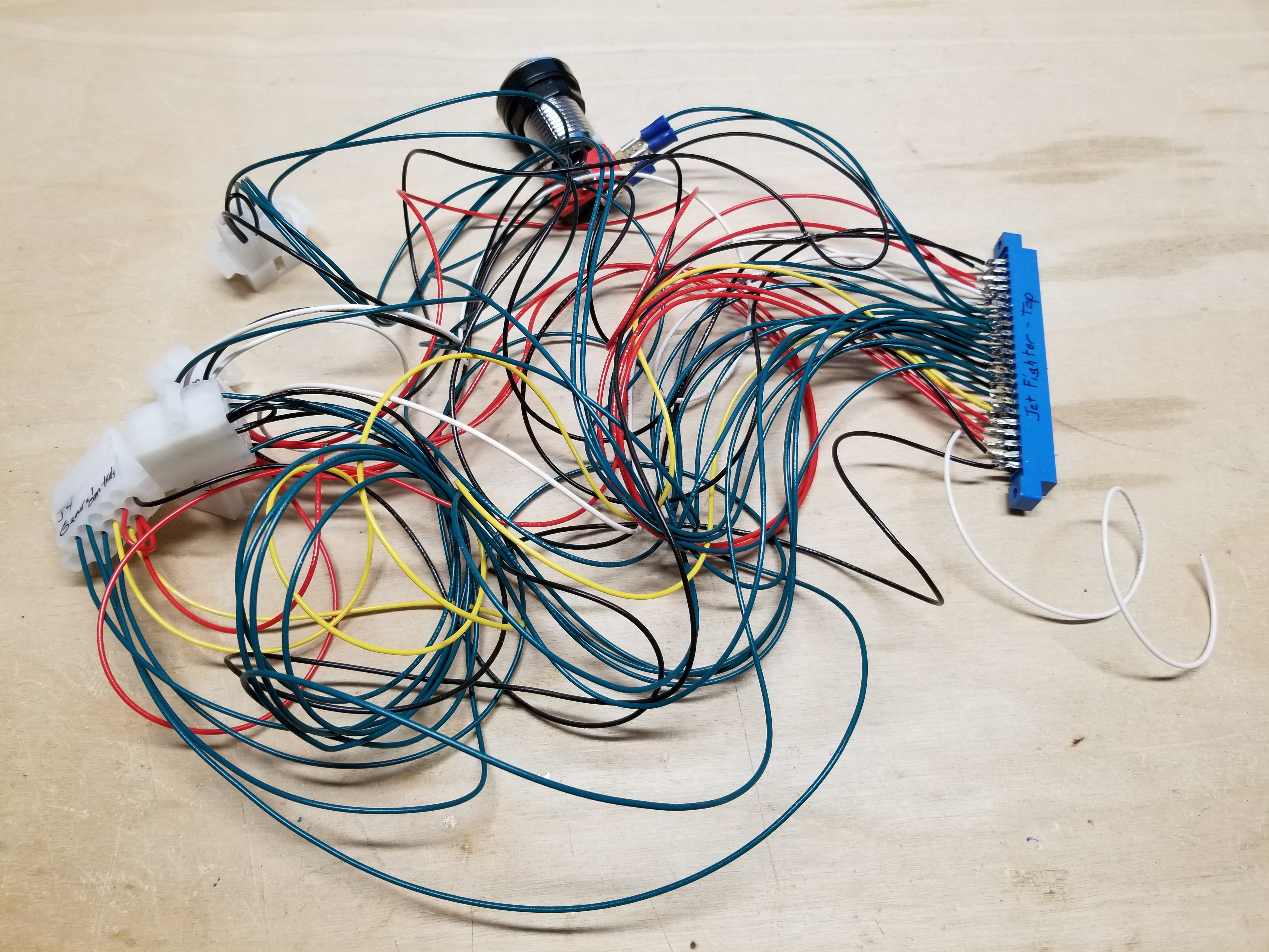
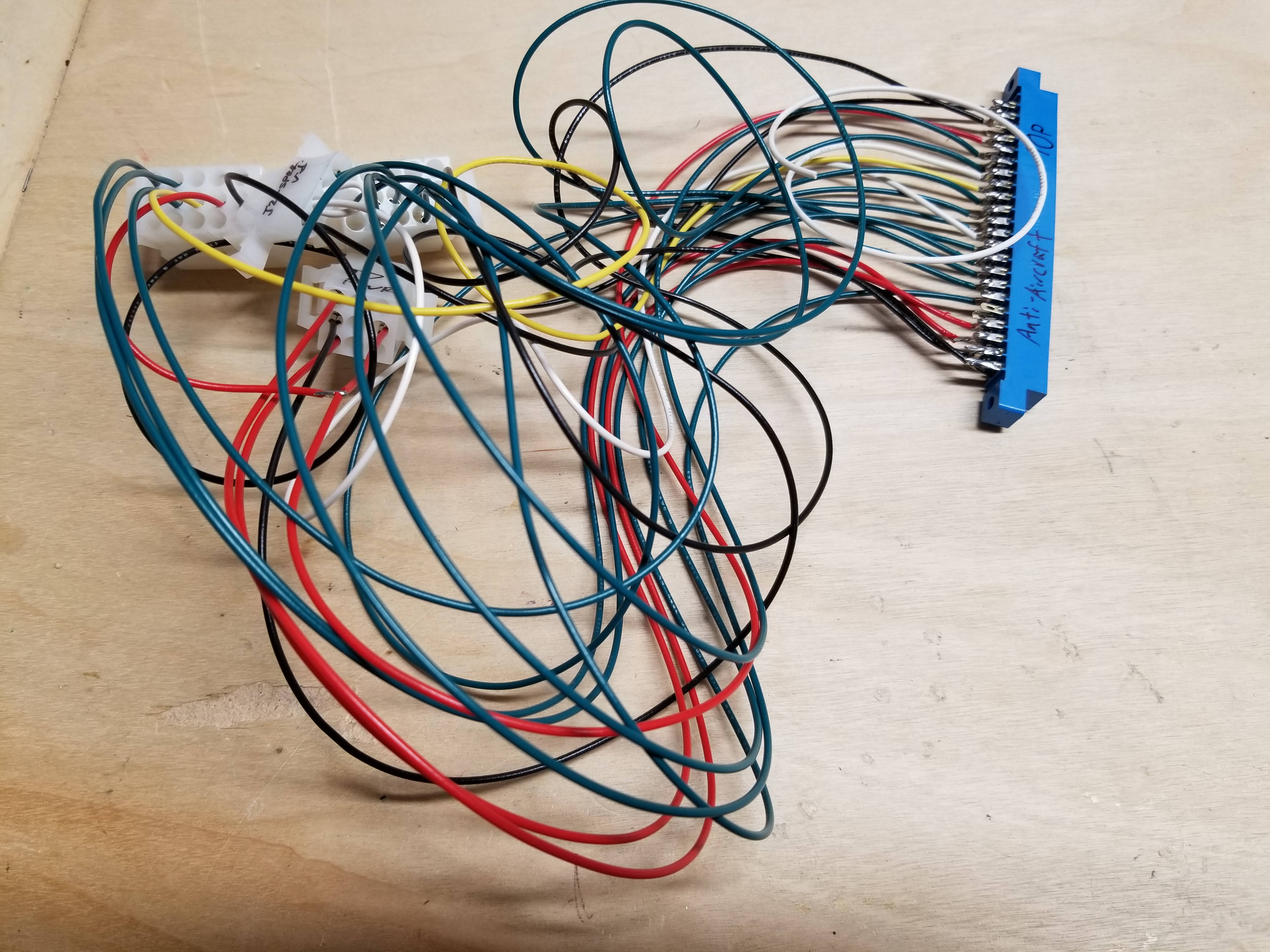
Here are the adapters I used to hook up the boards to my test rig.
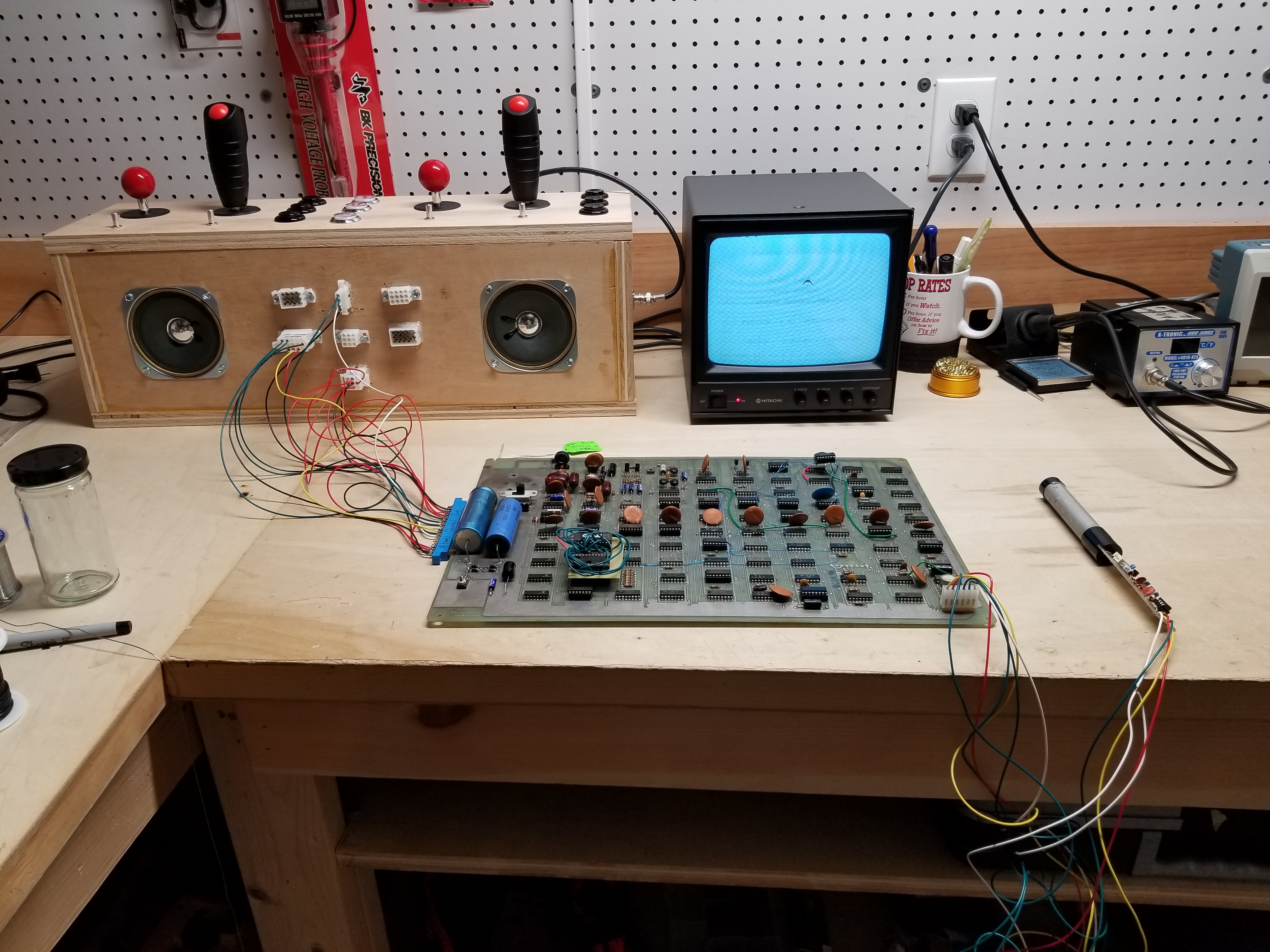
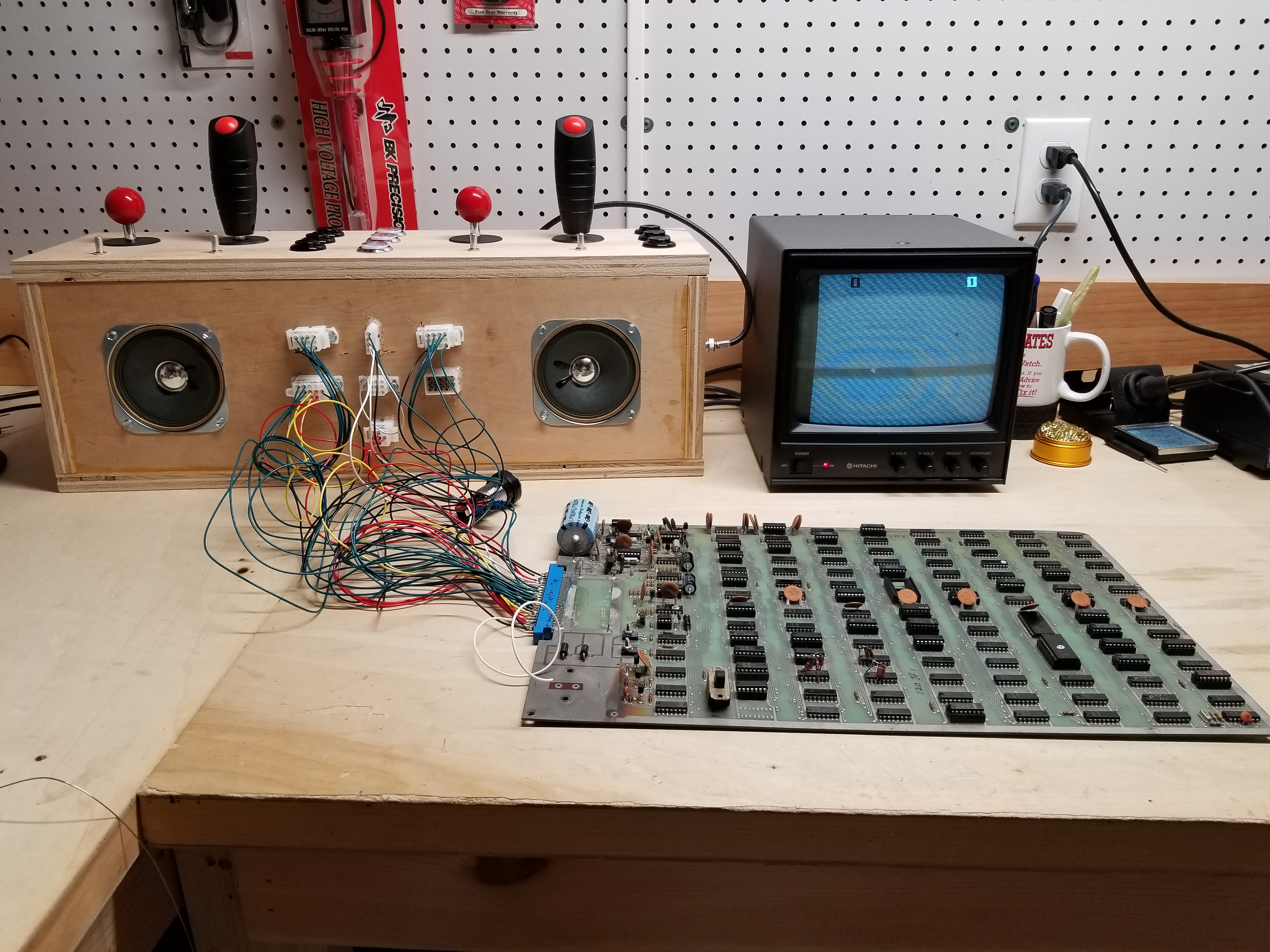
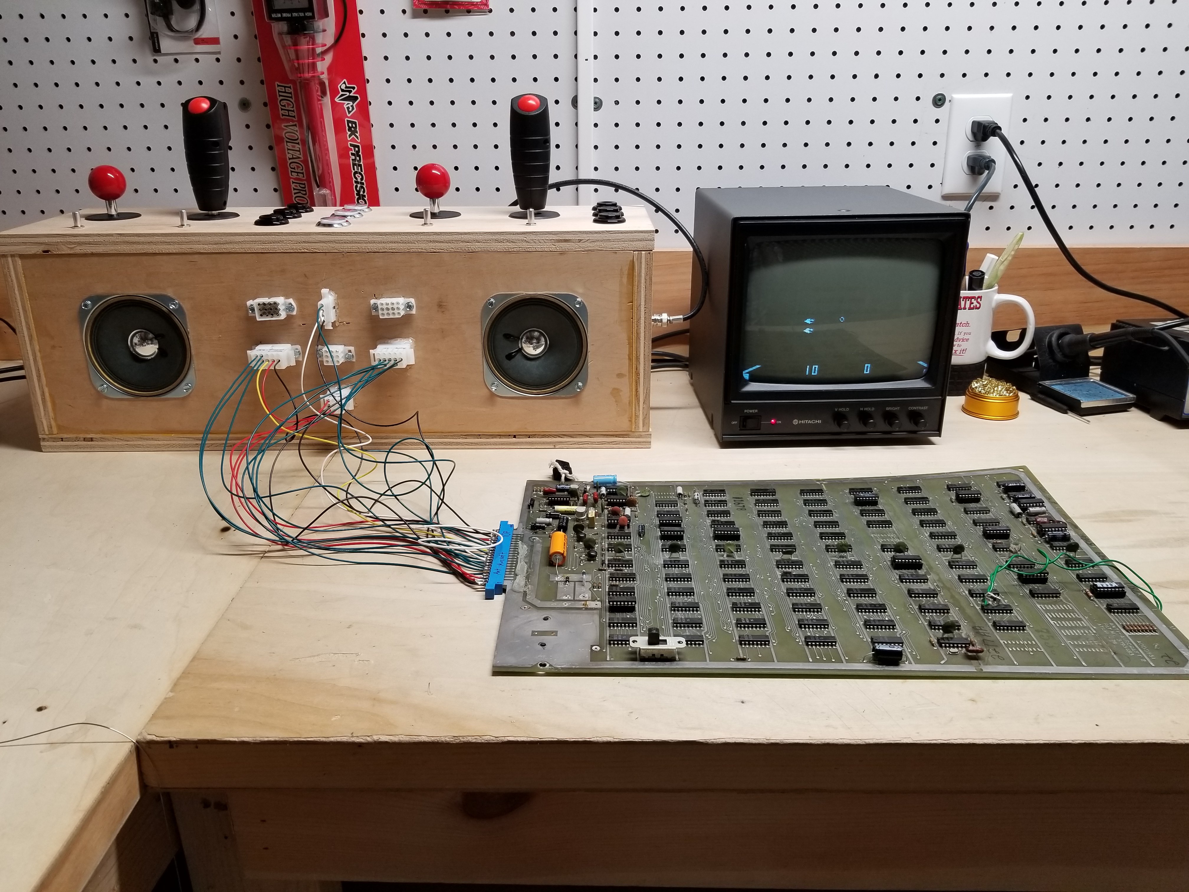
Here are some of my boards running on my test rig.
This page was published 8/30/2020
This page was last edited 8/30/2020